Filter Editor is where you create filters from components. Unlike the 'painting' approach common to all bitmap-editing applications, the Editor uses a 'node-based' approach – instead of modifying your image one step at a time like you do in bitmap editors, in Filter Forge you 'describe' what operations and in what order must be performed to produce the desired image. The operations are represented by components and the order of operations is defined by connections between them.
The Basic edition of Filter Forge doesn't let you save the filters that you create or edit. With these editions you can create new filters from scratch, or open and modify existing filters in the Filter Editor to have a look at their internals and learn how they work, but you cannot save them. See Filter Forge Editions for more information.

Here's how to find your way around the Editor:
- To pan the Workspace, drag it with the right mouse button. To zoom, use the mouse wheel.
- The Preview shows the output of the selected object.
- The Properties pane lets you adjust the properties of the selected object.
- To add components (see below) to the filter, drag them from the Components Bar to the Workspace.
- For more information about the Editor interface, see Using Filter Editor and Filter Editor Menu and Hotkeys.
Components
Components are the basic building blocks which you connect together to create a filter. Many components perform familiar operations such as blurs, color adjustments, distortions, and blending; others, such as elevation gradients or Perlin and Worley noises, might be less familiar. Each component can have multiple inputs, but only one output:
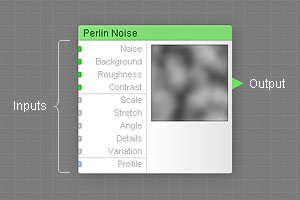
Each component can have multiple inputs, but only one output.
Here's what you need to know about inputs and outputs of components:
- Components can have multiple inputs, but only one output.
- Inputs accept connections that supply the component with the source data to process.
- Output sends the result to other components (via connections to their inputs).
- The color of the input slot (green, gray or blue) shows what types of connections it can accept – see Connecting Components below.
- If an input is unconnected, its value is defined by a corresponding parameter in component's Properties.
- Some components have required inputs which must always be connected.
- The number of inputs is fixed. The only exception is the Result component which has two sets of inputs.
How Components Work Together
Instead of modifying your image one step at a time like you would do in any bitmap editor, in Filter Forge you 'describe' what operations and in what order must be performed to achieve the desired result. The operations are represented by components and the order of operations is defined by connections between them. Components in a filter can be compared to workers on an assembly line – each component takes the input data supplied by 'upstream' components, processes them, and sends the result down the line to other components:
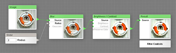
Components in a filter can be compared to workers on an assembly line.
In the above example, Filter Forge carries out the following instructions:
- Take the original image.
- Blur it (I'm not sure about the radius, so I want a slider to tweak it).
- After blurring, increase the contrast.
- We're done, give me the result.
Types of Components
There are three types of components in Filter Forge: map components, curve components and numeric components. Each component type performs a different class of tasks. The type of a component can be determined by looking at the color of its output triangle ('nose') or caption:
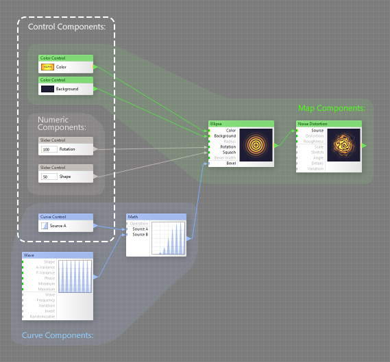
Map Components
Map components are the most important – they generate and process images. You cannot build a working filter without using map components. Examples of map components include Blur that blurs source images, Checker that generates checkerboard patterns, and Levels that adjusts the tonal range. Map components are called so because they provide a key ability called parameter mapping (see below).
Curve Components
Curve components generate, modify or combine curves. Examples of curve components include the Wave component that produces various waveforms, or the Stairs component that generates a stair-step curve useful for posterization effects. Curve components do not produce or modify images directly – they are used together with map components that have curve inputs. Examples of map components that can use curves are the Tone Curve component which performs the same function as the 'Curves' adjustment in Adobe® Photoshop®, or Profile Gradient which uses curves to define its gradient profile.
Numeric components generate numbers. Examples of numeric components include Slider, Value and Checkbox. They are a subtype of control components used to create the user interface which you see on the Settings tab in Filter Controls, so that anyone can tweak the filter without having to know what's inside. A single numeric component can affect multiple inputs of other components, and the way it affects them can be customized with remappers.
Control Components
filter users the ability to tweak filter settings without the need to open Filter Editor. Similar to other components, Control Components fall into three categories: Map components (like Color Control) can connect to map inputs only; Curve components (like Curve Control) can connect to curve inputs only, and Numeric Controls (like Slider) can connect to numeric inputs only.
Besides providing an interface to the Filter Controls, Control Components can also define group inputs when placed inside a group.
Parameter Mapping
Parameter mapping is one of the key concepts of the Filter Editor, understanding it is essential for building filters. As the name suggests, parameter mapping is done via map components and map inputs – actually, that is the reason why they are called 'Map Components' instead of 'Image Components'.
Mapping means defining component parameters with images (as opposed to controls such as sliders or checkboxes). When a parameter is mapped, its value can be different for different areas of the image, while a non-mapped parameter (whose value is defined by a checkbox or a slider) is constant throughout the entire image. Here's an example of parameter mapping:
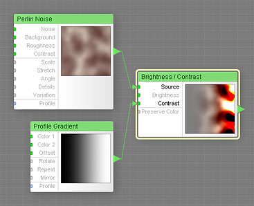
The Contrast level is mapped with a gradient.
In the above example, a black-to-white gradient is connected to the Contrast input of the Brightness / Contrast component – the Contrast level is mapped with a gradient. Since the Contrast parameter ranges from -100 to 100, black areas of the gradient correspond to the contrast of -100 (the left part of the thumbnail), white areas to the contrast of 100 (the right part of the thumbnail), and the gray levels in between to intermediate contrast levels.
For more information and examples of parameter mapping, see Map Inputs (section How Mapping Works).
Connecting Components
Connections between components always go from the output of a component to an input of another component, not the other way around. To create a connection, drag a line from the output triangle to the desired input. Both inputs and outputs are colored according to their type. The color of an input slot shows which type of components can be connected to this input. The rules of thumb are as follows:
- Green to Green: map components can be connected only to map inputs.
- Blue to Blue: curve components can be connected only to curve inputs.
- Gray to Anything: numeric components can be connected to any input (except required inputs).
The Result Component
The Result component is a special component which is always present in any filter. It serves as the end point, the final destination of connection flow, so it has no output triangle. The Result component also defines the filter type: Simple filters generally have a flat, 2D appearance, while Surface filters are rendered as 3D surfaces that support HDRI lighting and can produce bump and normal maps. Additionally, the Result component lets you access Filter Controls from within the Filter Editor.
